The other element seen on the reference line resembles a flag and is located where the leader line joins the reference line. SOLVED Back to AutoCAD Category.
Leader Lines Toolnotes
D All of the above.

. This MCQ question set of Engineering Drawing or Engineering Graphics contains two topics Intro to Engineering Drawings Graphics and Engineering Scale Introduction to Engineering Drawings Graphics 1. Drawing a line tangent to two circles. Our team delivers the power of the Digital Thread for Industry 40.
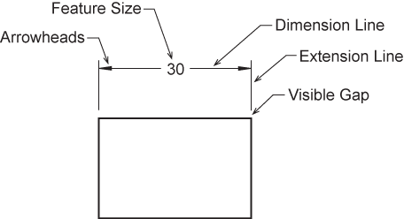
Dimension Text Guidelines Dimension text is placed in the middle of the line both horizontally and vertically. Will draw a Line one unit long vertically up in the Z direction of whatever the current Coordinate System is whether its the WCS or any other UCS. Word language Describe size location and specification of the object.
In the case of a Line specifically you can draw one on or parallel to the Z axis without changing the UCS. Dimensioning components Information to be dimensioned Extension and dimension lines and dimension number Leader. Back to Topic Listing.
Subscribe to RSS Feed. Industries eXcellence is a global division of the Engineering Group. Which tool can be used to draw a 90 degree angle.
Leveraging our unique experience implementing the entire spectrum of digital tools for industrial automation and process optimization we enable the adoption implementation integration and transformation journey. Basic Knowledge for Drafting Graphics language Word language Lec. This element is called a field weld and means the weld will be done in another location.
Next Filter by Labels. Dimensioning Methods Dimensions are represented on a drawing using one of two systems unidirectional or aligned. For instance from any point to.
Dimension Text Guidelines If the dimension text will not fit between the extension lines it may be placed outside them. Bhuiyan Shameem Mahmood. Bhuiyan Shameem Mahmood Graphics language Describe a shape mainly.
Arc Leader line and local note - Radius - Location of its center The letter R is written in front of a number to emphasize that the number represents radius of an arc. Which set of lead. Chapter 7 Dimensioning 2.
Chapter 07 dimensioning 1. For instance this weld may be applied at the job site not in the shop. Float this Topic for Current User.
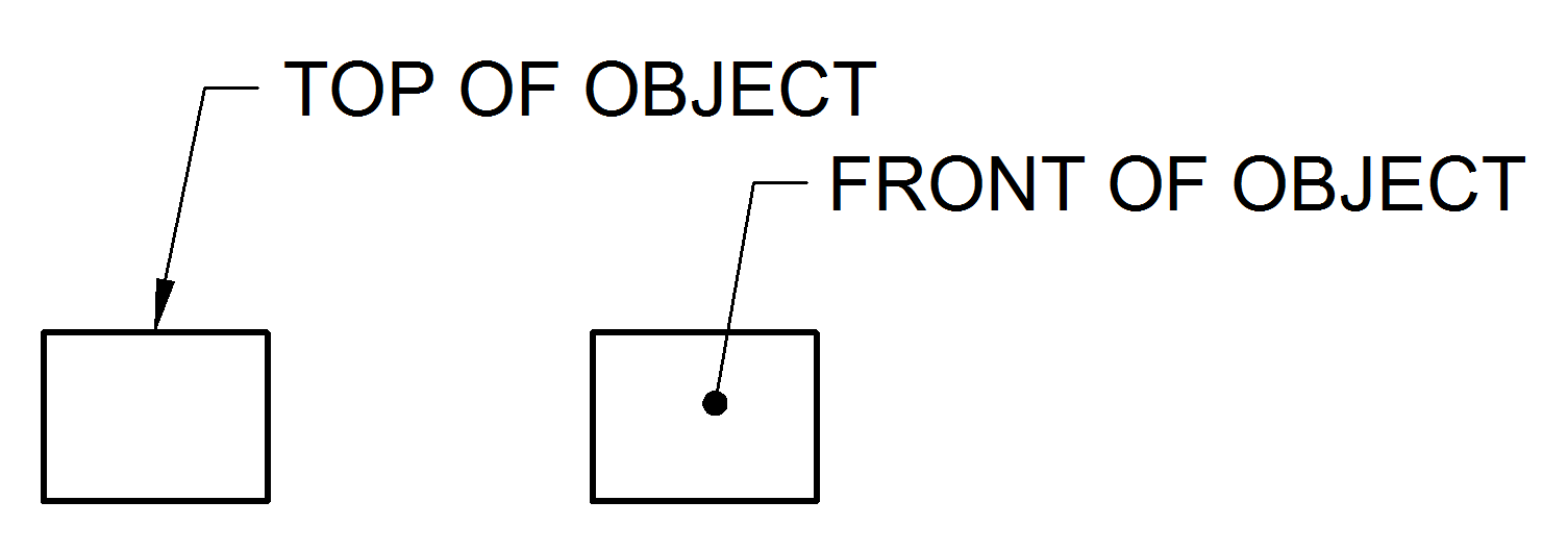
Mark Topic as New. Mark Topic as Read. Elements of Engineering Drawing Engineering drawing are made up of graphics language and word language.
Sometimes clarification will be given in the welding symbol tail or as a specification on the print. An engineering drawing is a type of technical drawing contains all the information of a product to be machined or fabricated the purpose is to specify the geometry necessary for the construction of the product. Line Arrow Head.
Standardized languages and symbols are used to describe the dimensions parameters and other features of the objects which helps people to understand.

Extension Lines Drafting Joshua Nava Arts

Technical Drawing Standards Leader Lines

Principles Of Dimensioning Engineering Design Mcgill University
Dimension Appearance And Technique

Engineering Drawing Dimensioning Part 1 Youtube

Technical Drawing Standards Leader Lines

Technical Drawing Standards Leader Lines
About Leader Objects Autocad 2021 Autodesk Knowledge Network
0 comments
Post a Comment